Right Ascension Drive and Slewing Assembly
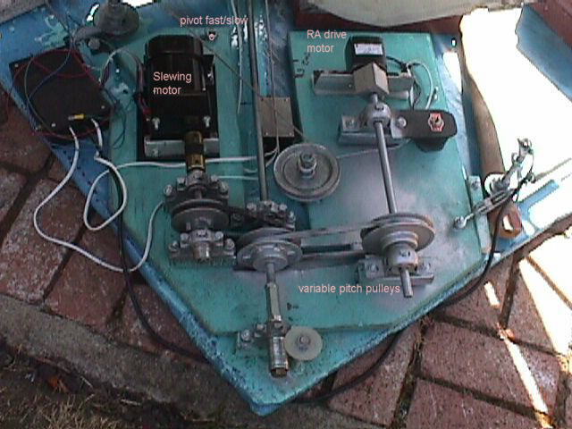 | The RA drive motor is a 1 rpm motor operating through a 3:4 pulley system to run the threaded rod at 1.33 rpm. The motor assembly is on a board which pivots to allow the slewing motor to turn the rod at several hundred rpm. Temporarily, the shifting mechanism is a lever which moves the board relative to the drive platform. Normal positioning is done by a spring which pulls the drive belt taut. This view is of the motor board from the north east corner. Click on the picture to enlarge. |
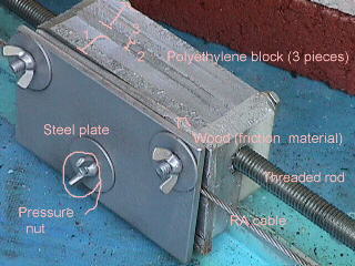 | The threaded shaft turns and moves a split nut constructed of 3 layers of polyethylene. A groove was cut in the 2 outside layers and a heated threaded rod was pressed into the groove to make the threads. As the rod turns, the nut moves to the left in this picture and pulls the cable that wraps around the RA wheel of the telescope. A rate of approximately 15 cm per hour is used. The rod is 1/2inch diameter, 13 threads per inch and requires a 40 second rotational period to match the diurnal motion of the stars. The clamping of the cable between the steel plate and the wood plate grabs the cable. When loosened, it allows the telescope to be moved in RA so that the range of the telescope is from 7 hours east of the meridian to 7 hours west. The uninterrupted tracking is about 7 hours. |
 | The threaded shaft is mounted on a 4 by 5 foot board prepped with fiberglass and resin. Seven pulleys route the RA drive cable from one side of the board to the other. A set of springs maintains tension. Weights are needed as the tension on the cable tends to make the board "float" and the weights keep tracking going smoothly. Lubrication of the 7 pulleys (the first 2 are shown in the figure) has reduced some jerkiness of the drive. The arrows in the figure show the direction of the cable in following the stars as the earth rotates. The split nut is just below the curved band that constitutes the RA drive wheel. This view is from the west.
|
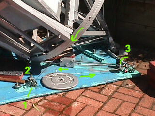
 | Pulleys 4, 6 and 7 are shown in this view of the drive board seen from the north east. The slewing and drive motors are noted as well. Pulley 5 is on an arm which connects to the spring and applies tension to the cable. The arrows show the cable and its direction of motion as the telescope moves west. Limit switches are at each end of the travel of the split nut. These switches turn off the power to BOTH the slewing motor and the clock drive. An over-ride push button is located on the control box.
Loosening the cable clamp will allow the nut to be moved to the end of the threaded rod allowing the telescope to track for the full 7 hour duration. |